
Ground Mount
MW-Scale Solar Design
Solyug Energy provides ground mount solar design at MW scale for utility developers, IPPs, and large C&I clients covering land layout, structural engineering, electrical design, and cabling for projects from single-digit MW installations to large utility-scale plants. Our utility scale solar design services are built on 520MW+ of solar design delivered across India, Africa, and the Gulf, giving us direct experience with the land, wind, and grid-interconnection variables that differ from site to site and country to country. Ground-mount MW-scale design is a different discipline from rooftop or smaller C&I work it requires topographic surveying, foundation engineering suited to real soil conditions, substation and MV/HV cabling design, and structural analysis for both fixed-tilt and single-axis tracker systems. This page covers what our large scale solar plant design process actually includes, and where we've delivered it.
Site-Specific Topography & Structural Safety: Utility ground-mount projects require rigorous 3D contour mapping, pull-out geotechnical testing, and wind load engineering. Solyug Energy provides end-to-end design covering pile foundation sizing, MV/HV substation evacuation, and fixed vs. single-axis tracker CAPEX/yield optimization for developers and EPCs.
Engineering Utility-Scale
Ground-Mount Solar Plants
A ground mounted solar structure design at MW scale carries engineering demands that don't apply at smaller project sizes. Land isn't a fixed, known quantity the way a rooftop is it needs topographic surveying, soil testing, and drainage planning before layout can even begin. Structural loads scale with row length and system type (fixed-tilt racking behaves differently under wind load than single-axis trackers). And grid interconnection at MW scale typically means MV/HV substation design, not a simple LT grid tie-in. As a MW scale solar EPC design company, we treat these as engineering problems to be solved with real site data not generic template layouts scaled up from smaller projects. Every ground-mount MW-scale design we deliver starts with the land itself, not an assumed panel count.
MW-Scale Solar Projects Delivered
Utility-scale buyers research extensively before making contact specific, numbers-led proof points matter more here than general capability claims. Explore our delivered project engineering track record below across ground-mount, tracker, and C&I captive plants.
Integrated Engineering Flow
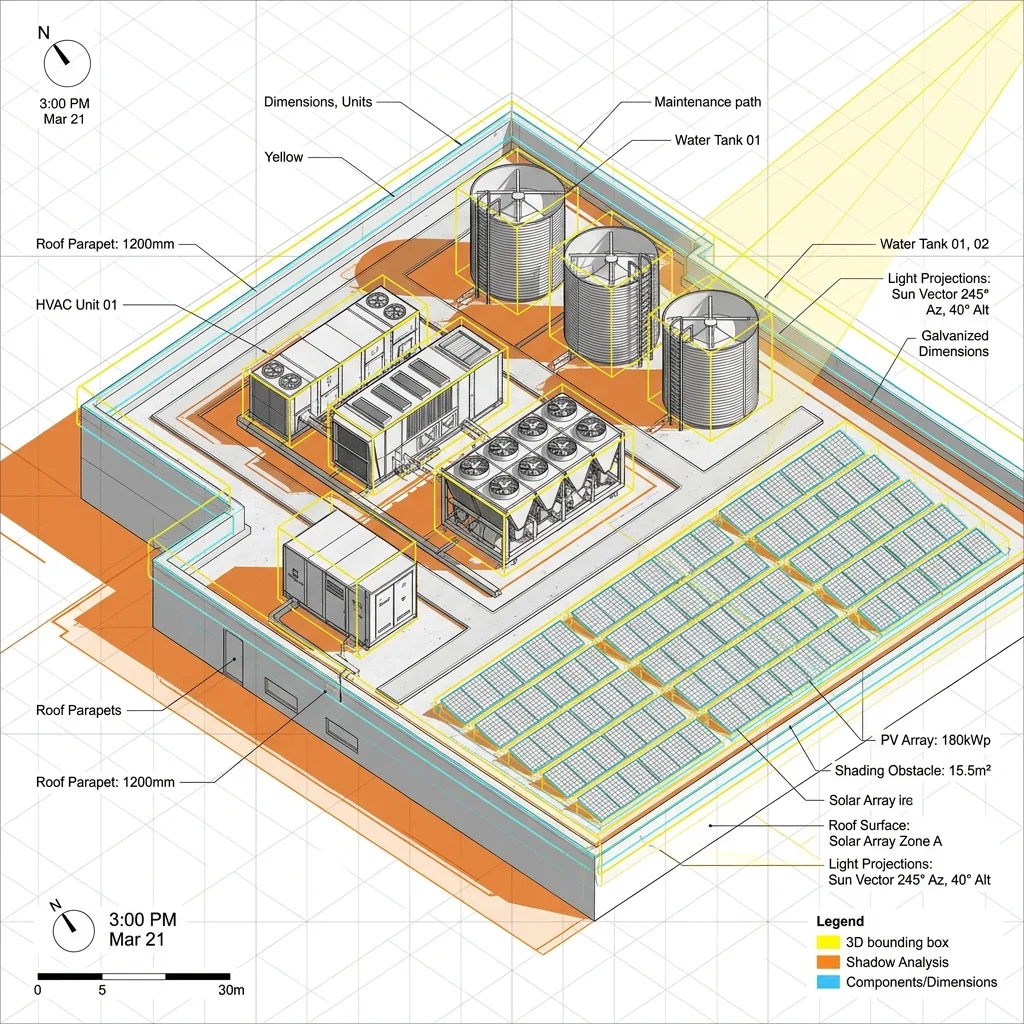
Terrain Contouring & 3D Shade Simulation
Have an Upcoming MW-Scale Plant?
Consult our engineering team for land layout planning, PVsyst P90/P95 simulation, and STAAD Pro structural design.
Delivered Engineering Track Record
Proven engineering execution across ground-mount, tracker, and high-capacity solar installations.
| Project Type | Capacity | Location | Year | Scope Delivered |
|---|---|---|---|---|
Ground-mount, fixed-tilt | [XX MW] | [State], India | [20XX] | [GA layout, structural, electrical DED] |
Ground-mount, single-axis tracker | [XX MW] | [Country], Africa | [20XX] | [Full DED + STAAD Pro wind analysis] |
Ground-mount, C&I captive | [XX MW] | [Country], Gulf | [20XX] | [Layout + shadow analysis + BOQ] |
What We Deliver for MW-Scale Projects
No Cont

No Cont
Topographic survey-based site layout and land-use planning
No Cont
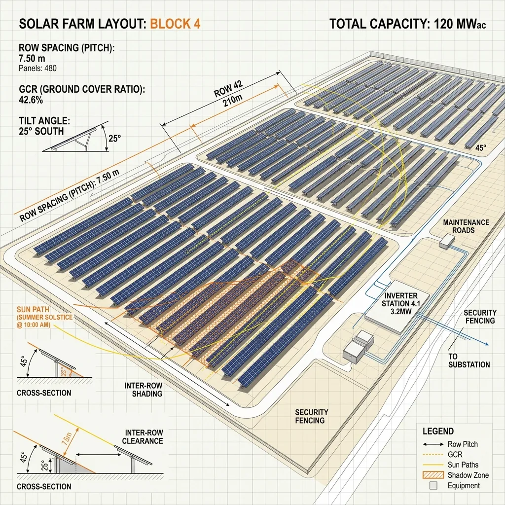
Row spacing and inter-row shading optimization across the full plot
No Cont
Structural design for fixed-tilt and single-axis tracker mounting systems
No Cont
STAAD Pro wind load analysis suited to the project's specific region
No Cont
Foundation design based on site-specific soil conditions
No Cont
MV/HV cable routing and substation layout for grid interconnection
No Cont
Complete electrical design (SLD, string sizing, protection coordination)
No Cont
Bill of Quantities (BOQ) for accurate procurement at scale
Land Layout & Row-Spacing Optimization
Topographic & Land-Use Layout
MW-scale ground-mount design starts with a topographic survey of the site elevation changes, drainage patterns, existing vegetation, and access constraints which directly shapes how much of the plot can actually be used for panel placement versus roads, drainage channels, and buffer zones. Sites that look uniform on satellite imagery frequently have grading or drainage requirements that meaningfully affect usable area and foundation costs, which is why this step happens before layout is finalized, not after.
Row Spacing & Inter-Row Shading Study
Row spacing (pitch) is optimized to balance land utilization against inter-row shading losses, particularly during winter months when the sun angle is lower. Tighter spacing fits more capacity onto a given plot but increases shading losses between rows; wider spacing reduces shading but requires more land per MW installed. We model this trade-off specifically for each site's latitude and land constraints rather than applying a fixed industry-standard spacing across every project.
Structural Design for Fixed-Tilt & Tracker Systems
Structural design differs meaningfully between fixed-tilt racking and single-axis tracker systems trackers introduce dynamic loading and additional structural and control considerations that fixed-tilt systems don't have. We design and validate both system types, matching the structure choice to the project's land characteristics, budget, and generation targets.
Foundation & Structural Design
Foundation type (driven pile, screw pile, ballasted, or concrete footing) is selected based on actual soil test data for the site, not assumed uniformly across the project. Structural design is then validated through STAAD Pro wind load analysis specific to the project's wind zone, ensuring the mounting structure whether fixed-tilt or tracker meets safety margins for the region's actual wind conditions rather than a generic national standard.
MV/HV Cable Routing & Substation Layout
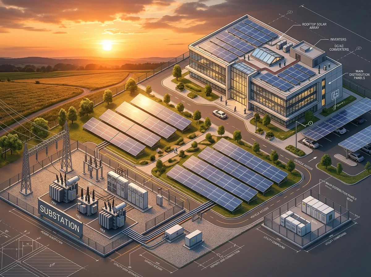
At MW scale, grid interconnection typically requires medium-voltage (MV) or high-voltage (HV) infrastructure rather than a simple LT connection. We design MV/HV cable routing across the site along with substation layout transformer placement, switchgear location, and the interconnection point coordinated with the project's grid connectivity study and interconnection agreement requirements.